A few months ago, I bumped into this post from Veronica Explains about her “writerdeck.” The idea really intrigued me because I was suffering from constant distraction, and my writing frequency was dropping harder than the stock market.
If you haven’t heard of writerdecks before, they are essentially single-purpose devices dedicated to writing. Often this means very limited hardware and software to keep the device minimal and distraction-free. People have been using old laptops, Kindles, or anything that can put characters on a blank screen, except for pen and paper. There’s a whole community for this kind of device, and they gather around a subreddit called /r/writerdeck. Their solution to the age of distraction was to lock themselves into an environment where there’s nothing else to do but write. Whether this actually works or not, there was only one way for me to find out.
Why build?
I first looked into commercially available devices advertised on /r/writerdeck just in case I could just throw money at the problem & get something cheap. But they usually cost around ~$250 - $900+ (USD). And they all came with their own keyboard. Only BYOK is a reasonable device at $199. But they use LCD rather than E-ink. Not a big deal, although I quite like to reduce my blue-light exposure so I decided to make something simple for myself.
Screen size
The screen size of a writerdeck can vary a lot for different purposes. Some prefer a small horizontal screen to keep the content short and easy to follow; others prefer a taller screen for screenplays. There’s really no one size that fits all.
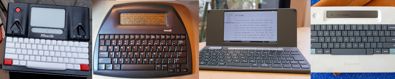 Source: writerdeck.org
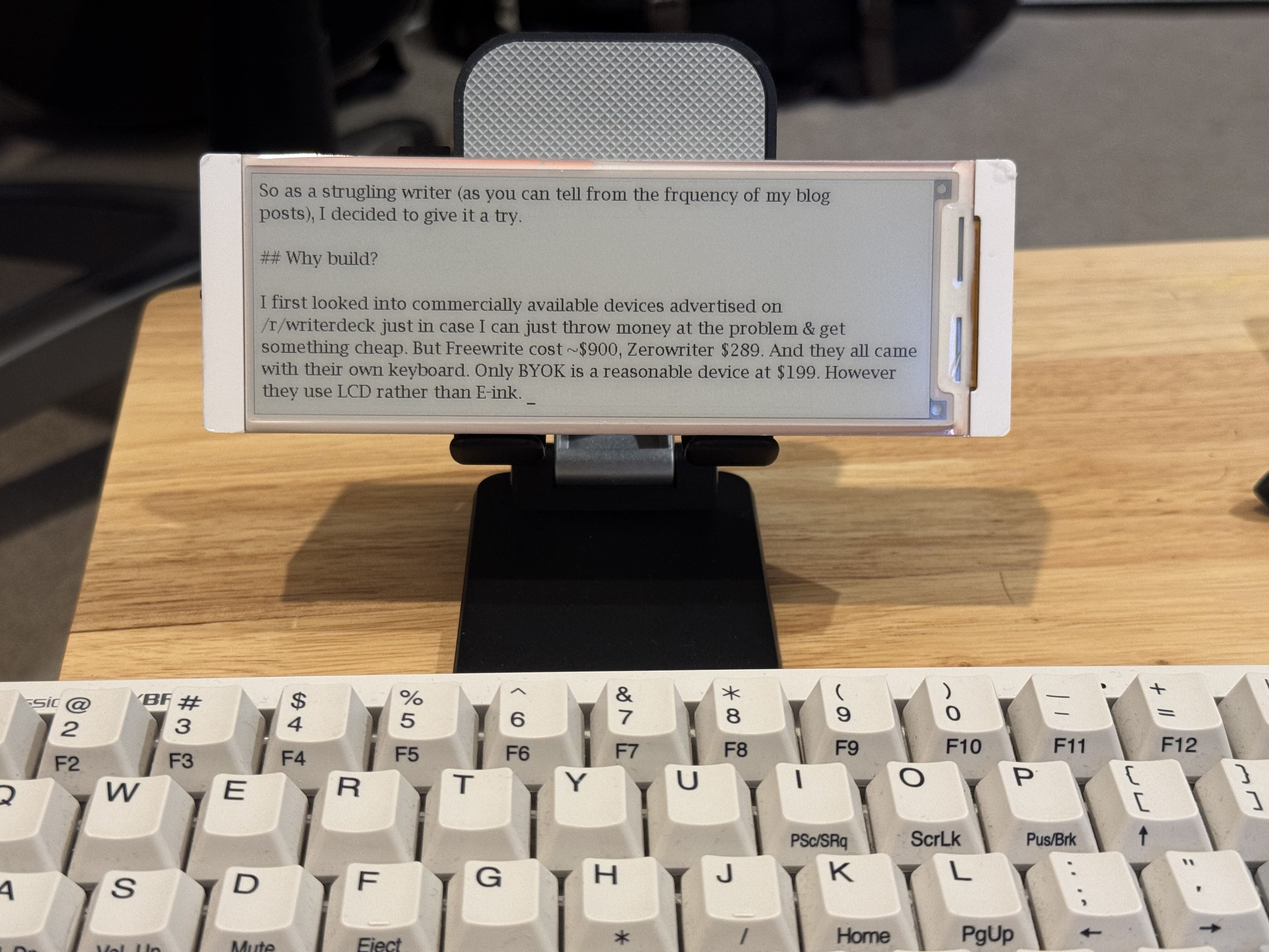
I write short stories and blog posts, so vertical space doesn’t give me that much benefit. It actually makes writing harder because I keep coming back to edit what I just wrote. So in the end, I went with a 5.79” e-ink display that was intended for price tags in supermarkets. It’s a simple board with ESP32 S3, black-and-white (no grayscale) e-ink. It’s got Bluetooth and Wi-Fi built in; powerful enough to handle my sporadic writing sessions.
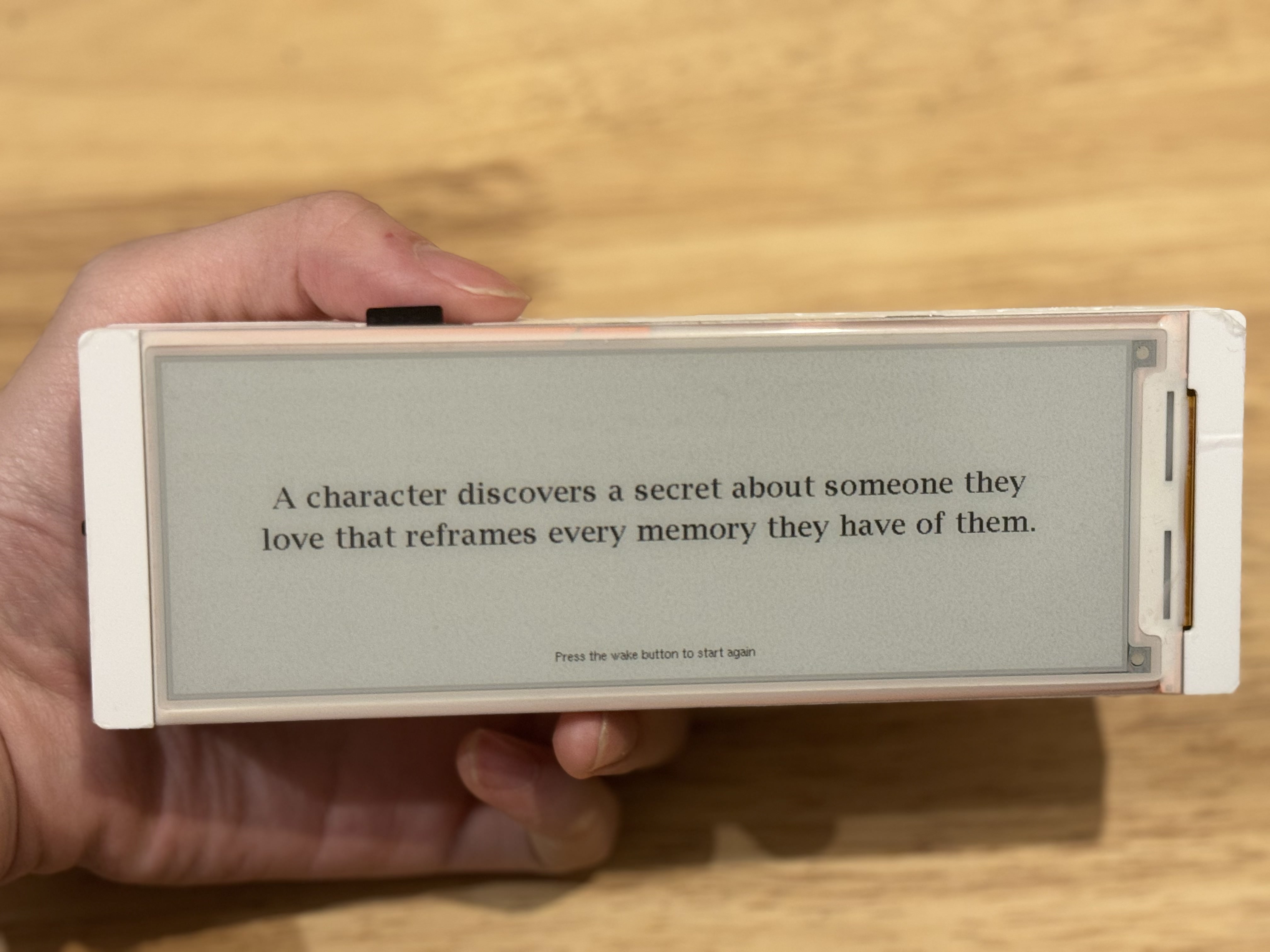 It can show a writing prompt as the screensaver
The case
Part of the reason why I decided on that board was because everything is already soldered on one board. The display is hooked to the ESP32 S3 chip and battery charging is handled via USB-C so I could just write my own firmware for it and don’t have to worry about soldering a bunch of electronic parts just to get the screen going.
But in the end, I still had to get a LiPo battery from AliExpress, which cost me around $7. The battery has an SH1.25 connector, which was different from the SH1 connector on the board, so I ended up buying a whole bag of SH1.25 connectors too.
The structure of the board is quite simple. There are 3 main layers:
- The board on top with the display.
- The middle plate with cut out holes for the protruding components.
- The backplate which is a plain flat piece of plastic screwed onto the board.
Luckily, it came with a detailed 3D design file. All I had to do was open the design in FreeCAD, watch a few YouTube videos to learn how to extract the backplate as an .obj file, and import it into KiCad (since it’s simpler to learn).
I decided to swap out the backplate for a custom 3D-printed case that can be used to also hold the battery.
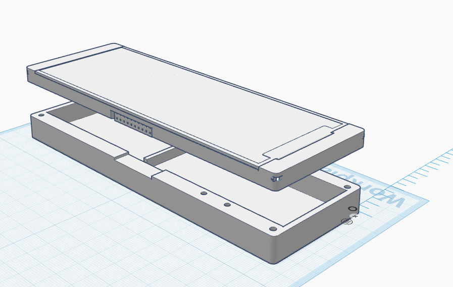
The rest of the work was convincing a friend with a 3D printer to print out my case (shoutout to Alan if he’s reading).
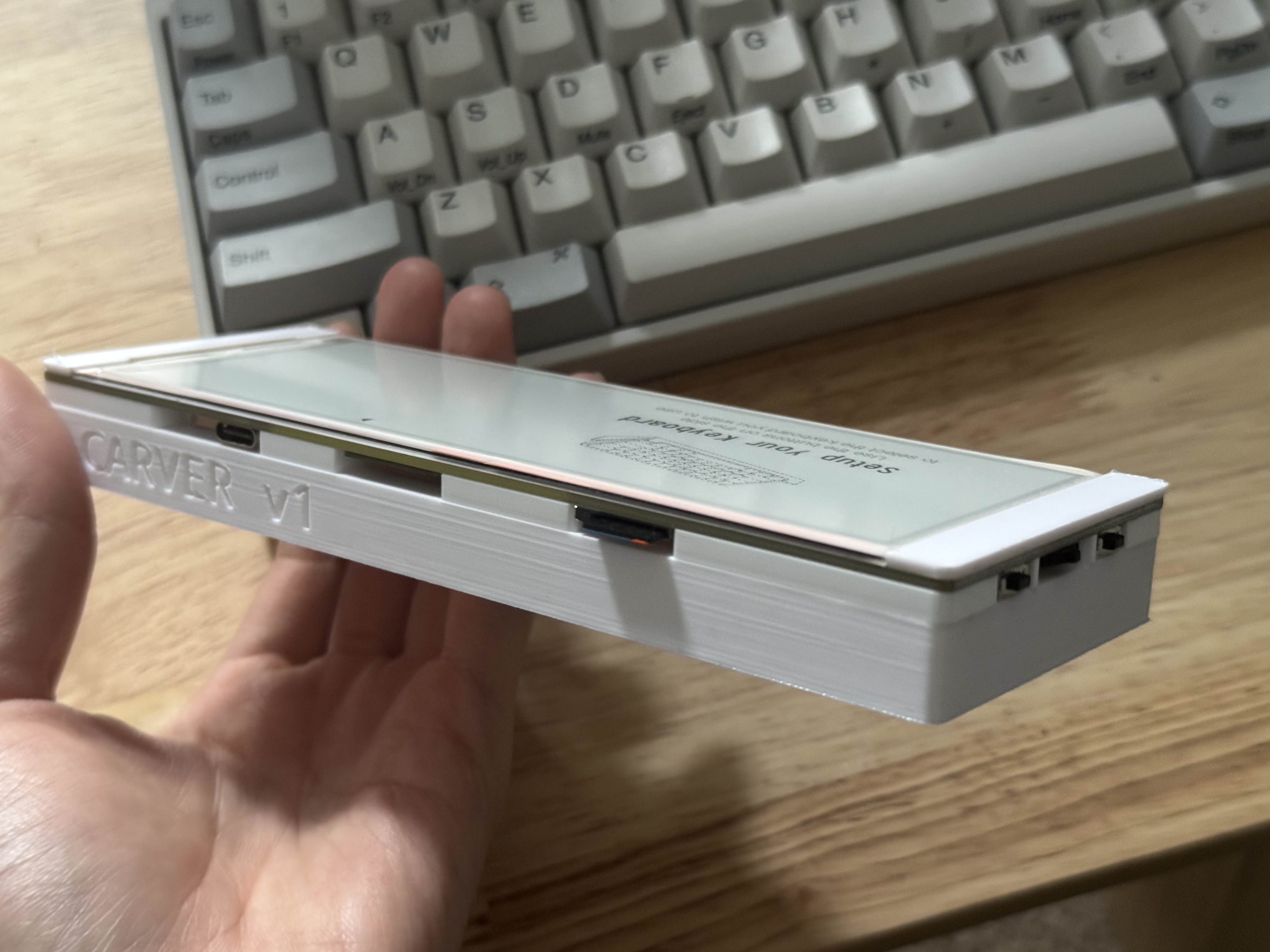
Display driver
This is the hardest part of the whole building process.
The board came with some sample code written in C using Arduino IDE. But I don’t know C and I also hated how slow Arduino IDE takes to compile my program. So I had no choice but to write the firmware in Rust.
Except there was no driver for this display in Rust. There was one library, but it’s for a different hardware and initially didn’t work on my display at all. So I had to fork it, and threw Claude into the deep end.
After a few nights burning tokens, Claude & I came out with working code, and even comments explaining how the driver works … in Mandarin. I used to think vibe coding wasn’t really a problem as long as I could read and understand the code, but this time I truly had no idea. I cannot claim any credit for this work. I was, in fact, burning credits on this work :) I wonder what the world will look like when what I was doing becomes normalised one day.
Anyway, with the code all compiling, I flashed it on the board and oh my god it worked!??!?!
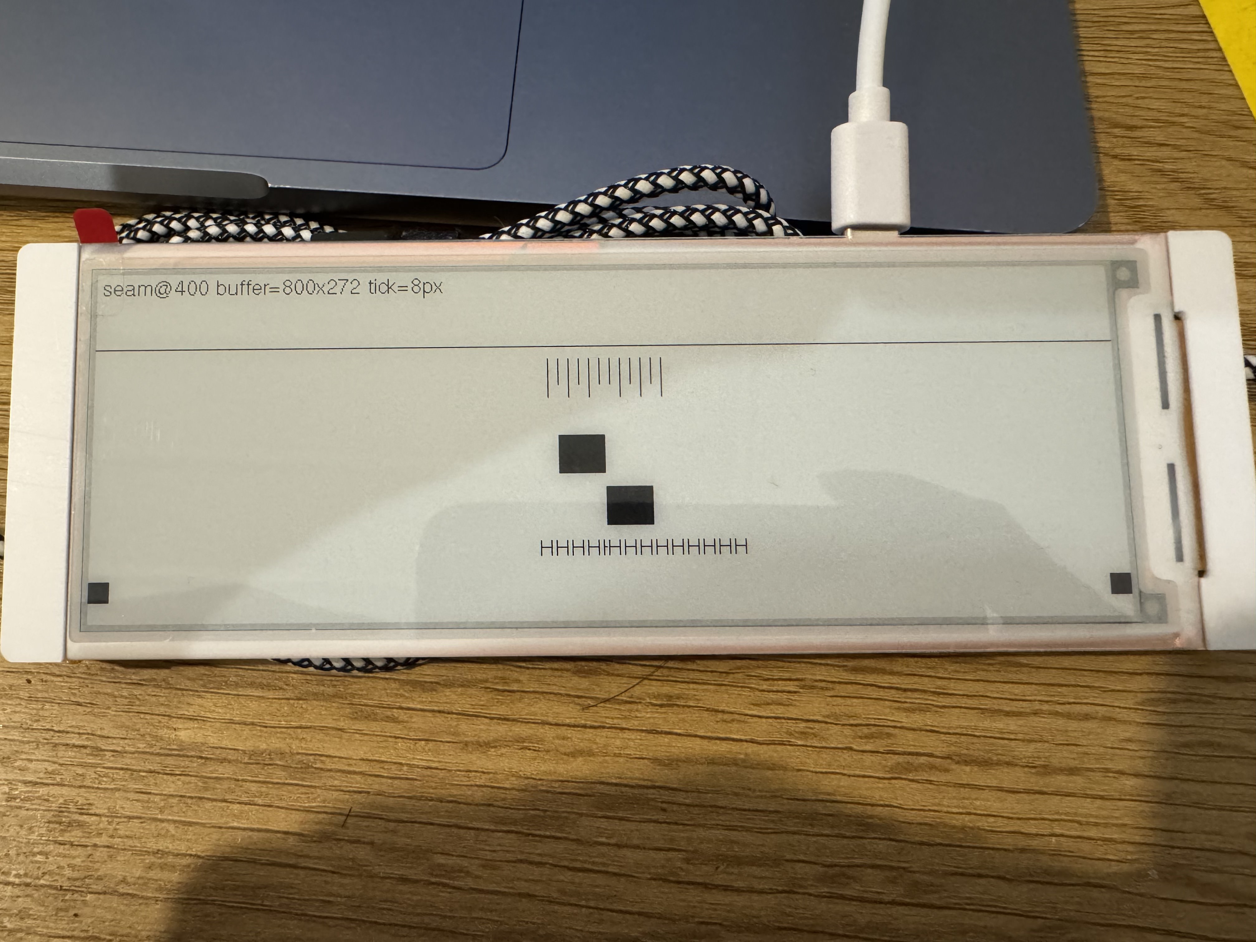
I tried rendering all kinds of things for a few nights, but there was always this weird missing column at the middle of the screen. Claude was thinking in circles and couldn’t figure out why.
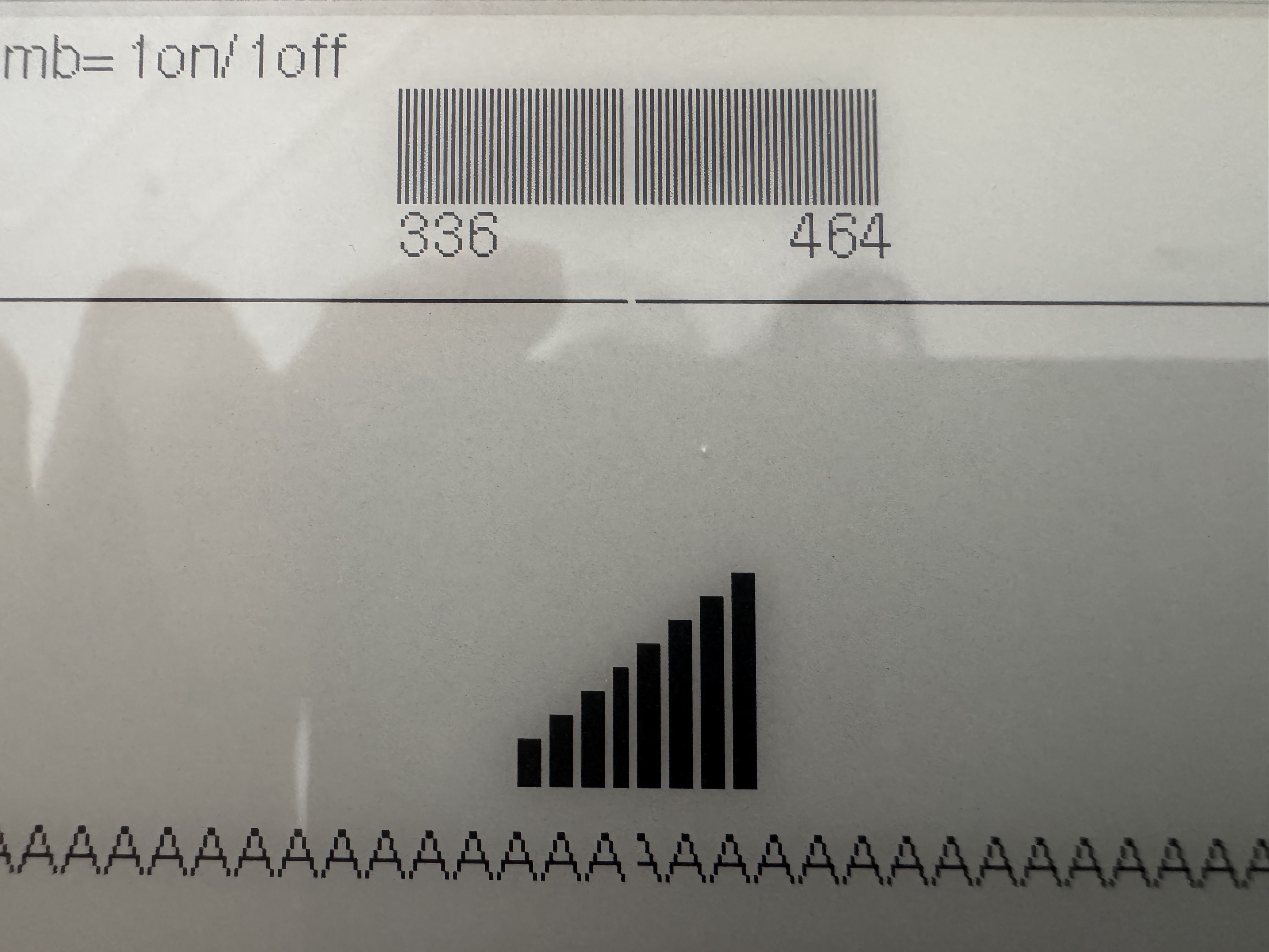
So I ventured out to the Internet and found this blog post, which pointed out that there are two smaller e-ink screens underneath. There is a master screen and a slave screen, and they share the same pixel column in the middle so all I needed to do was to send the same byte to the two chips. Everything then worked perfectly.
Bluetooth
There are two kinds of Bluetooth: Bluetooth Classic and Bluetooth Low Energy (BLE). The difference between them is that Bluetooth Classic maintains the connection all the time, draining the battery more quickly, whereas BLE alternates between sleep and wake, making it more energy efficient.
To connect to Bluetooth keyboards, I went with the BLE implementation. Typing isn’t a continuous thing so most of the time the Bluetooth connection can stay asleep until a burst of keystrokes arrives. Also, ESP32-S3 only supports BLE :P
But the main pain is really from the pairing method. With BLE, you’ve got the legacy pairing and secure connection pairing, which was introduced after legacy pairing. I still don’t know if my HHKB actually does secure connection pairing, but right now, only legacy pairing seems to work for me.
The problem is esp-radio, the library for interfacing with Bluetooth and Wi-Fi on the ESP32, only supports modern secure connection pairing, so I had to combine that with trouble-host, which has some dependency conflicts with esp-radio and in the end, I had to fork the entire esp-hal repo to customise it for my firmware. I won’t bore you with the details but just a warning that if you’re going down the same road, you’ll hit the same pothole.
Battery
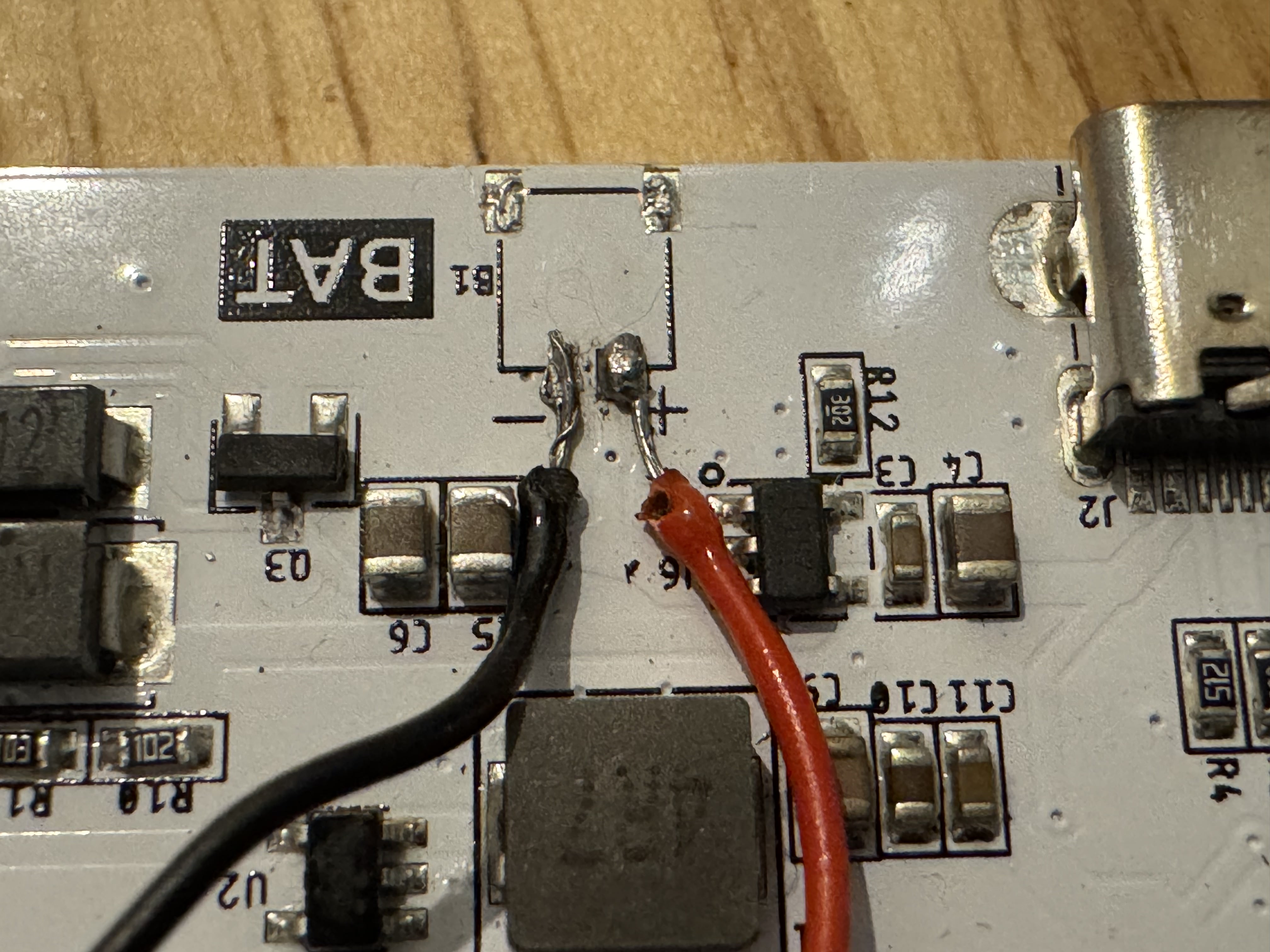
A few days later, the writerdeck worked great. It got Bluetooth talking to my HHKB. It also showed my writings on the display and used a microSD card to store them. I was pretty happy with how things turned out. However, I didn’t want to have my writerdeck always connected to my laptop for power. I had to connect the battery to the board! So I soldered a new battery connector to the board, and accidentally recreated the Chernobyl elephant foot.
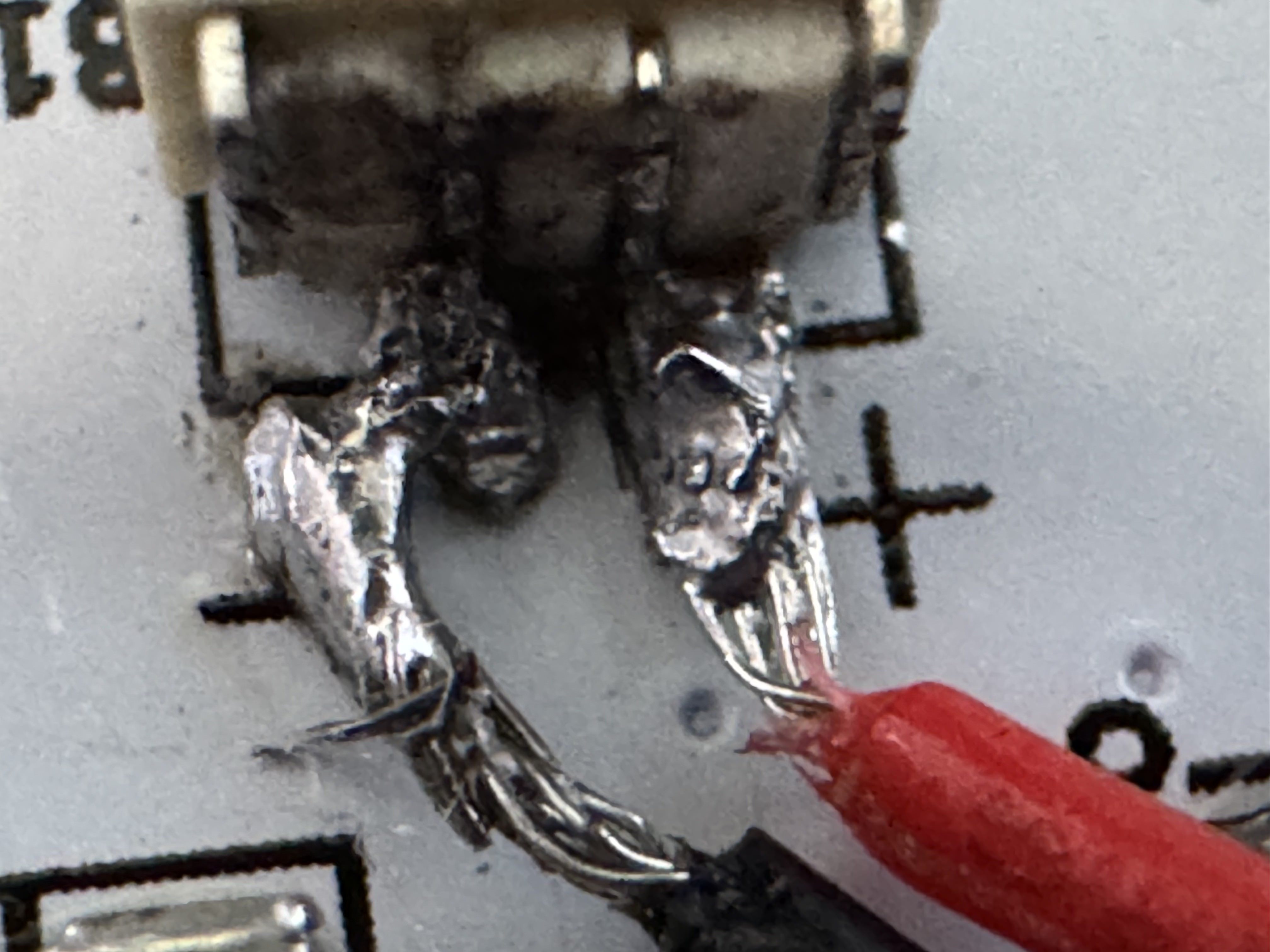
The idea was pretty simple: I was going to monkey patch the new SH1.25 connector to the back of the existing SH1 connector on the board. But the tiny joints were a massive pain to work with, plus I burnt off a big chunk of the SH1 connector so I ended up just removing it completely for easier soldering.
Things looked pretty good after that:
However, while the board does support charging, it had no component that can measure the current battery level. After a bit of research, I found out that you can just measure the voltage that the battery gives off to estimate how much power it still has.
The trick is that electricity flows from positive, through to ground. But before it does that, we connect a GPIO ADC input so it can read the voltage from the battery.
┌───────┐
│  BAT  │
└───┬───┘
    │       ┌───────┐
    ├───────┤ GPIO  │
    │       └───────┘
┌───┴───┐
│  GND  │
└───────┘
Because there’s no resistance from ground, electricity just flows straight to ground, skipping GPIO, so we have to add a resistor between GPIO and ground.
┌───────┐
│  BAT  │
└───┬───┘
    │
    │       ┌───────┐
    ├───────┤ GPIO  │
┌───┴────┐  └───────┘
│ 100 kΩ │
└───┬────┘
    │
┌───┴───┐
│  GND  │
└───────┘
And because the GPIO can’t take high voltage from the battery (the ESP32 ADC has an input range from 0 - 3.1V), we have to put another resistor between the battery and GPIO.
┌───────┐
│  BAT  │
└───┬───┘
    │
┌───┴────┐
│ 100 kΩ │
└───┬────┘  ┌───────┐
    ├───────┤ GPIO  │
┌───┴────┐  └───────┘
│ 100 kΩ │
└───┬────┘
    │
┌───┴───┐
│  GND  │
└───────┘
Knowing the value of these two resistors, we can calculate the voltage level using the formula:
V(out) = V(in) * (R2 / (R1 + R2))where:
V(in)is the battery voltageV(out)is what GPIO receivedR1&R2are the resistors
or simplify that when we know R1 = R2:
V(out) = V(in) / 2Using the voltage values that LiPo batteries typically give, we can map V(in) to the battery percentage. But of course, since this isn’t a linear graph, we can only approximate the percentage.
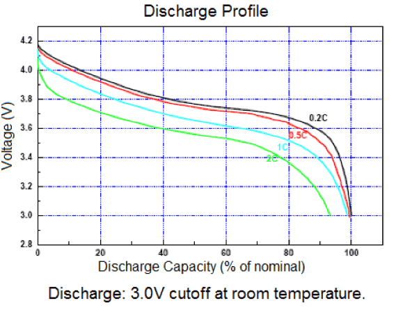 Source: learn.adafruit.com
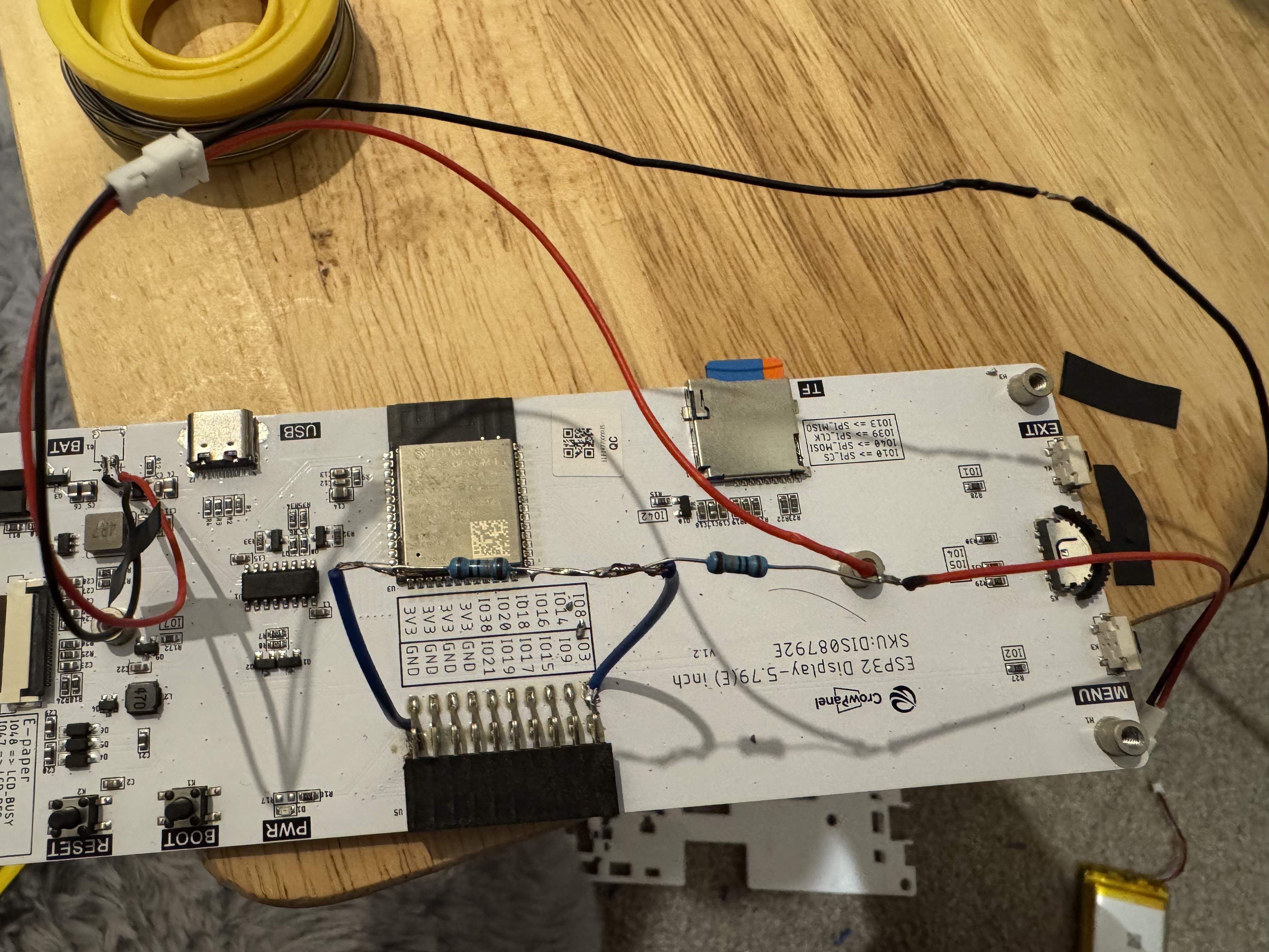
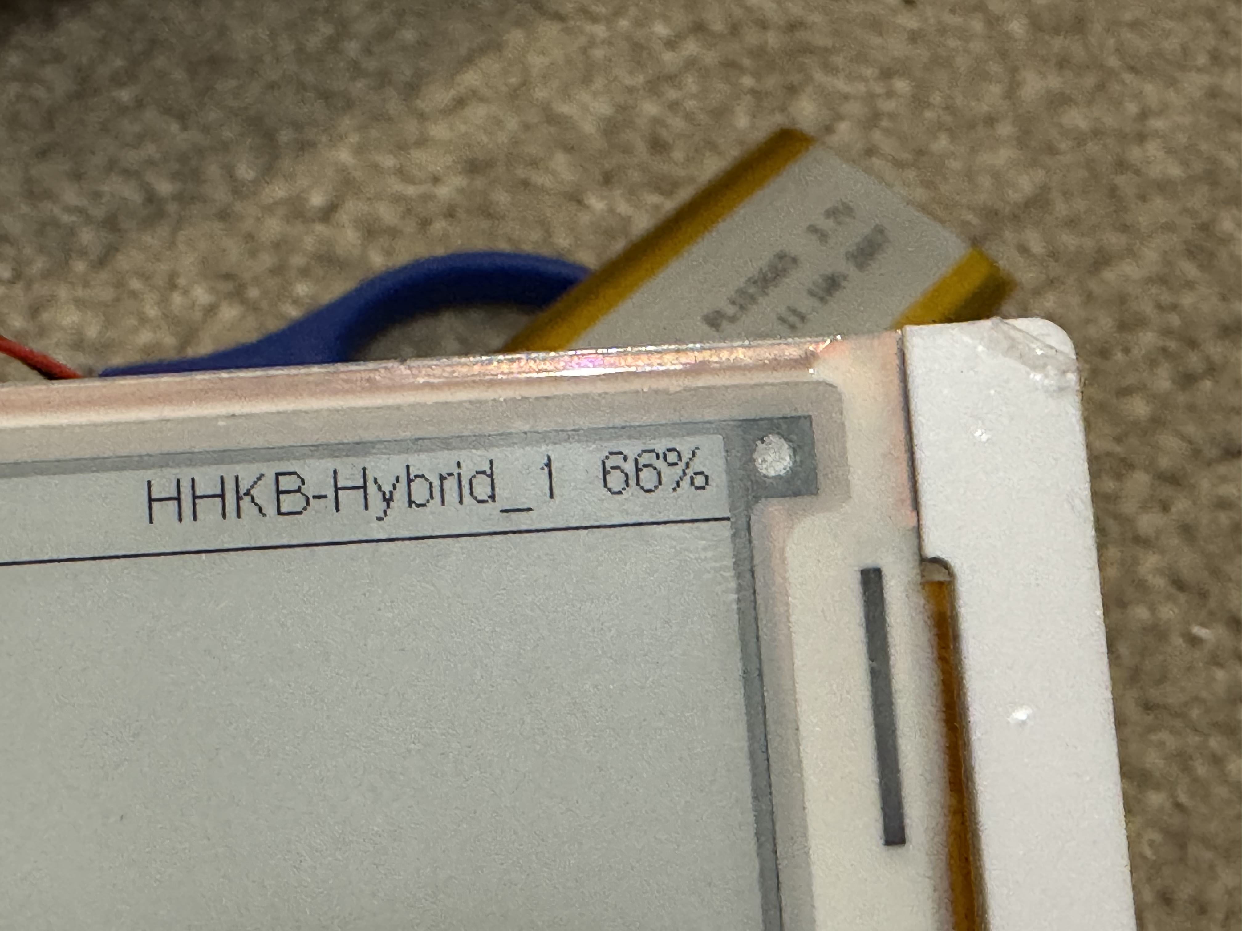
Overall, this is a simple voltage divider circuit. After a few minutes of soldering, I got myself some battery percentage showing on the screen!
That’s it
That’s pretty much what it takes to build a writerdeck. As a weekend project, I’d give it a 9/10: it wasn’t too difficult, and I still learnt plenty of things. What mattered more was that I could actually see this device becoming a part of my life. It wasn’t some side project that gets finished and tossed away. I’d definitely bring this along when I’m out writing at cafes or travelling to other countries (hopefully TSA doesn’t have a problem with my DIY-writerdeck-that-is-not-a-bomb-but-can-potentially-be).
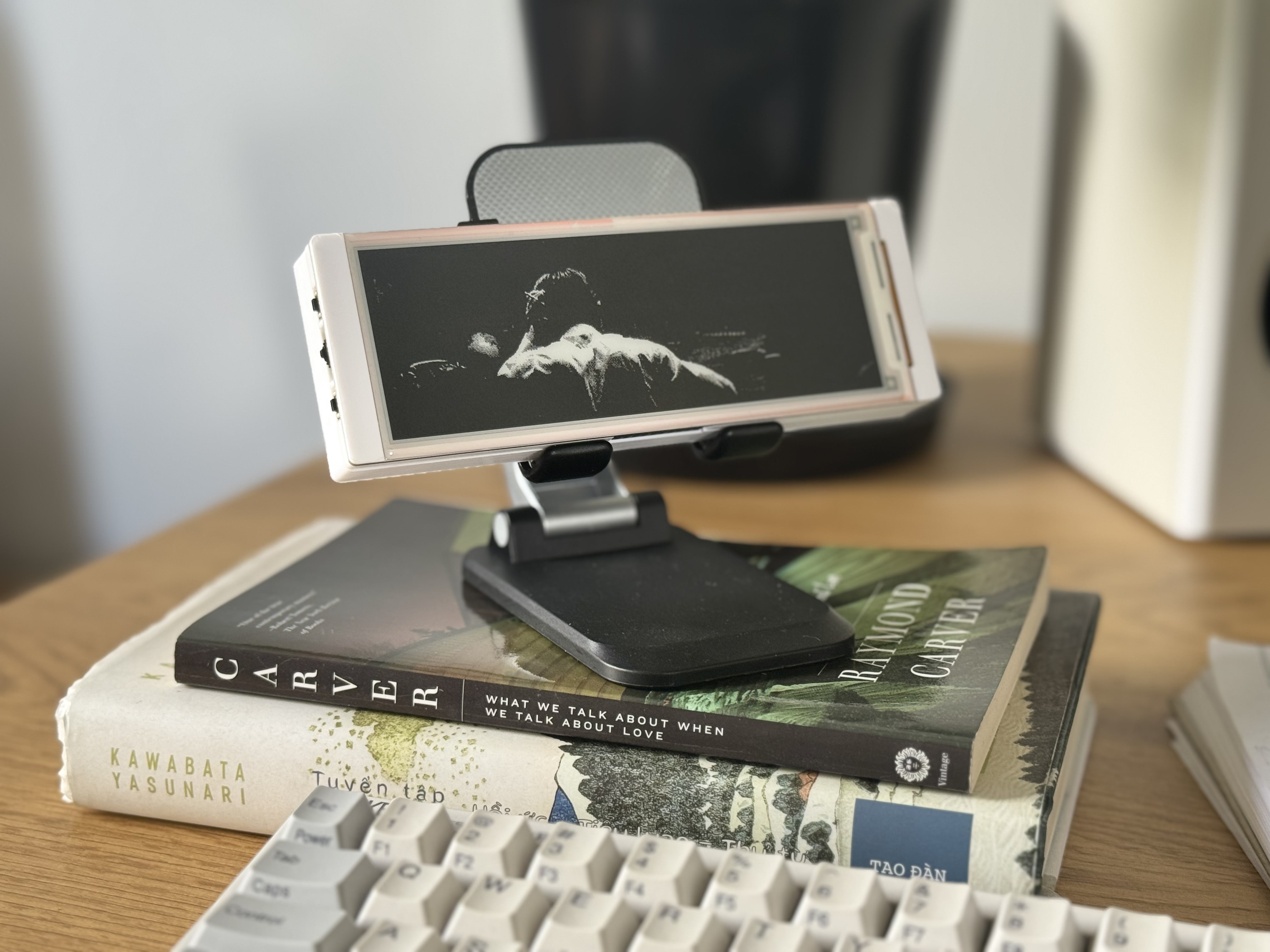 It shows a save screen while sleeping to save power.
Overall, I’m really pleased with how things worked out. The device works great (this post was drafted on it) despite the display taking ~400ms to update on each keystroke. But I don’t really consider that a problem. It somehow feels a bit like writing by hand. When I’m writing with a pen, my hand often can’t keep up with my thoughts, so I end up thinking the same thought two or three times. Sometimes that’s frustrating, but sometimes it also reveals little things that I would have missed if I hadn’t slowed down.